|
|
Users Guide | Patterns Reference | WebsydianExpress | Search |
|
|
Users Guide | Patterns Reference | WebsydianExpress | Search |
The model structure required by Websydian leads to useful diagrams. Below is outlined a simple example Web Application to illustrate how the corresponding AllFusion Plex Diagram provides a good overview of the application.
The example used to illustrate this point allows the user to list some items from a database, add new items to the list and delete items from the list. To keep the example simple, an item cannot be changed once it has been added.
The application consists of three pages:
Conforming to the function structure required by Websydian, the following functions are defined:
The Event Handler function responsible for cancelling is refered by using comprises because it is shared between the Add page and Delete page.
The call structure of the example is straightforward:
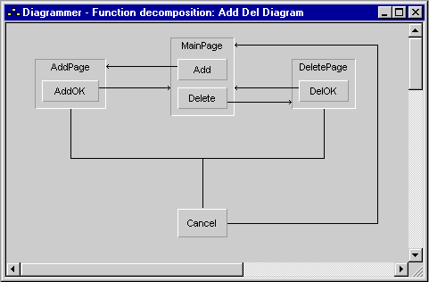
The example application described above yields the following AllFusion Plex diagram:

The point here is that the diagram tells quite a bit of the story described so laboriously above:
Basically, all of the fundamental structure of the application can be shown using the AllFusion Plex Diagram Editor.
Just like any other AllFusion Plex application, it is sometimes advantageous to do parts of the development of a Websydian application by using the Diagram Editor. In the initial stages of the development, not least because you tend to structure the application by using the web pages as the organizing principle anyway, this approach lets the developers maintain a high-level view on the entire application.
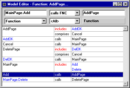
For reference, the figure below shows a Model Editor listing the triples corresponding to the diagram above:

The triple declarations of the example application defined above.